
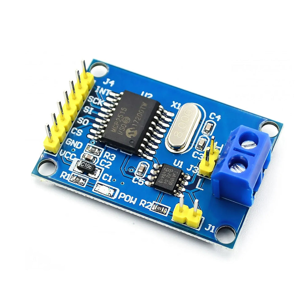
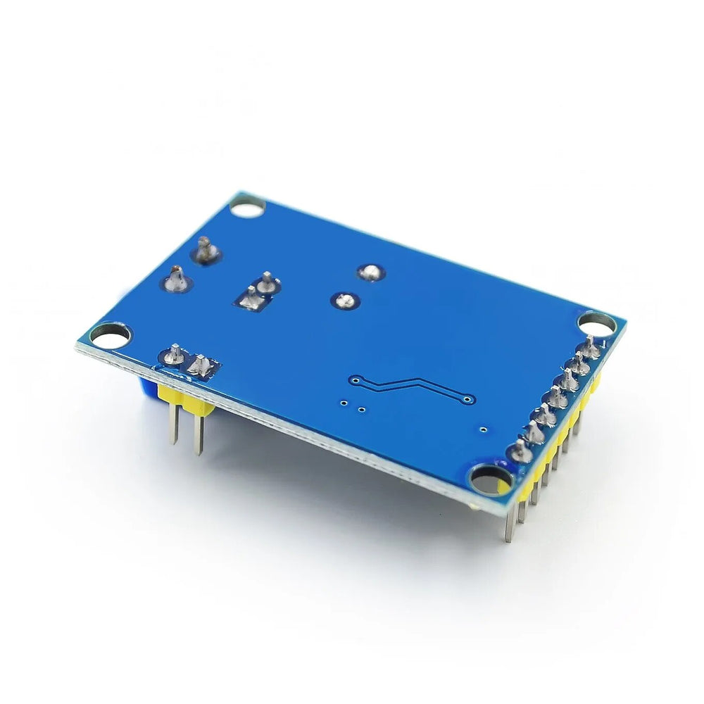
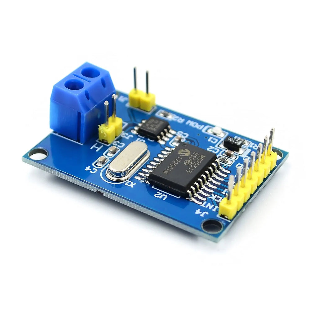
MCP2515 CAN Bus Controller
MCP2515 CAN Bus Controller has a 5-10 day lead time before dispatch. Order will only be sent once all items are available for delivery.
MCP2515 CAN Bus Controller
The MCP2515 CAN Bus Module adds full CAN 2.0B networking to microcontrollers that don't have a built-in CAN peripheral, such as the Arduino Uno, Nano and Mega. It pairs Microchip's MCP2515 stand-alone CAN controller with a TJA1050 high-speed transceiver on a single compact board, so you only need an SPI connection and two bus wires to join or build a CAN network. It's well suited to automotive diagnostics, robotics, industrial sensor networks and multi-board projects that need reliable, noise-resistant communication.
Key Features
- Complete CAN node: MCP2515 controller plus TJA1050 transceiver on one board, with screw terminals for CANH and CANL.
- CAN 2.0A/B support: Standard (11-bit) and extended (29-bit) identifiers, plus remote frames, with 0 to 8 byte data fields.
- Speeds up to 1 Mbps: Supports all common bit rates including 125, 250, 500 kbps and 1 Mbps.
- Protocol handled in hardware: Arbitration, CRC checking, error handling and retransmission are managed by the MCP2515, so your MCU only sends and receives complete frames.
- Hardware filtering: 6 acceptance filters and 2 masks let the module ignore irrelevant traffic, reducing load on your microcontroller.
- Buffering: 3 transmit buffers and 2 receive buffers.
- SPI interface: Up to 10 MHz, with an interrupt (INT) output for efficient message handling.
- Selectable termination: Onboard 120 Ω termination resistor enabled or disabled with a jumper.
- Strong library support: Works with popular Arduino libraries including mcp_can, arduino-mcp2515 and ACAN2515.
Specifications
| CAN Controller | Microchip MCP2515 |
| CAN Transceiver | NXP TJA1050 |
| Protocol | CAN 2.0A (11-bit) and CAN 2.0B (29-bit) |
| Bus Speed | Up to 1 Mbps |
| MCU Interface | SPI (up to 10 MHz) + INT |
| Crystal | 8 MHz |
| Operating Voltage | 5 V DC |
| Buffers | 3 transmit, 2 receive |
| Filters | 6 acceptance filters, 2 masks |
| Termination | 120 Ω, jumper selectable |
| Dimensions | Approx. 44 x 28 mm |
How to Use
1. Wire the module to your Arduino. For an Arduino Uno or Nano:
- VCC → 5V
- GND → GND
- CS → D10
- SI (MOSI) → D11
- SO (MISO) → D12
- SCK → D13
- INT → D2
2. Build the bus. You need at least two nodes, each with its own module and microcontroller. Connect CANH to CANH and CANL to CANL, and make sure all nodes share a common ground. Use twisted-pair wire for anything longer than a breadboard setup.
3. Set termination. The bus needs a 120 Ω terminator at each physical end. With two nodes, fit the termination jumper on both modules. With more nodes, fit it only on the two at the ends.
4. Install a library. Install the mcp_can library (by coryjfowler) from the Arduino Library Manager.
5. Initialise with the correct crystal and speed. This module uses an 8 MHz crystal, so make sure your code specifies MCP_8MHZ. Every node must use the same bit rate.
#include <mcp_can.h>
#include <SPI.h>

MCP_CAN CAN0(10);  // CS on D10

void setup() {
  Serial.begin(115200);
  if (CAN0.begin(MCP_ANY, CAN_500KBPS, MCP_8MHZ) == CAN_OK) {
    Serial.println("MCP2515 initialised");
  } else {
    Serial.println("MCP2515 init failed");
  }
  CAN0.setMode(MCP_NORMAL);
}

void loop() {
  byte data[8] = {0x01, 0x02, 0x03, 0x04, 0x05, 0x06, 0x07, 0x08};
  CAN0.sendMsgBuf(0x100, 0, 8, data);  // ID 0x100, standard frame, 8 bytes
  delay(1000);
}
6. Test. Load the library's receive example on the second node and open the Serial Monitor. If frames with ID 0x100 appear, your network is working.
Note for 3.3 V boards: This module runs at 5 V, so its SPI output (SO/MISO) is at 5 V logic. When using it with an ESP32, Raspberry Pi or other 3.3 V device, use a level shifter on the MISO line.
Frequently Asked Questions
What is the MCP2515 and what does it do?
The MCP2515 is a stand-alone CAN 2.0A/B controller from Microchip that connects to a microcontroller over SPI. It handles CAN framing, arbitration, error checking and filtering, so your MCU only has to send and receive complete CAN frames rather than deal with bit-level protocol details.
What's the difference between the MCP2515 and the TJA1050 transceiver?
The MCP2515 is the digital CAN controller. It understands the CAN protocol and talks SPI to your MCU. The TJA1050 transceiver converts the controller's logic-level TX/RX signals into the differential CANH/CANL voltages on the physical bus. This module includes both chips on one board.
Do I need one MCP2515 per node on the CAN bus?
Yes. Each CAN node without a built-in CAN controller needs its own MCP2515 and transceiver. A single module can't be shared across multiple microcontrollers, as every logical CAN node requires its own controller.
Why is my MCP2515 module not working with Arduino?
The most common causes are:
- The library is configured for the wrong crystal (16 MHz instead of 8 MHz)
- Different CAN bit rates set on each node
- Missing or incorrect termination (120 Ω at both ends only)
- CANH/CANL swapped, or no common ground between nodes
- INT pin not wired, or the wrong CS pin defined in code
Checking these points solves the majority of issues.
What is the maximum speed and cable length for an MCP2515 CAN network?
The MCP2515 supports classic CAN speeds up to 1 Mbps. Usable cable length depends on bit rate and wiring quality. Typical rules of thumb are around 40 m at 1 Mbps and up to roughly 1000 m at 50 kbps with proper twisted-pair cabling and termination. The limit comes from the CAN bus itself, not the MCP2515 specifically.
Can I use the MCP2515 with an ESP32, or should I use the ESP32's built-in CAN (TWAI)?
You can use the MCP2515 with an ESP32 over SPI (with a level shifter on MISO), but in most cases you don't need to. The ESP32 has a built-in CAN controller called TWAI, so you usually only need to add a 3.3 V CAN transceiver such as the SN65HVD230. The MCP2515 is most useful when your microcontroller has no CAN peripheral at all.
How many messages can the MCP2515 handle under heavy load?
The MCP2515 has two receive buffers. On a busy bus, if frames arrive faster than your MCU can read them over SPI, additional frames will be dropped. For moderate traffic, such as sensor data at 10 to 100 Hz, it performs well. Using the hardware filters and the INT pin helps considerably. For very heavy traffic or tight real-time requirements, a microcontroller with a built-in CAN controller and deeper FIFOs is a better fit.
What cables and connectors should I use?
- Twisted-pair cable with roughly 120 Ω characteristic impedance
- 120 Ω termination at both ends of the bus
- Secure, locking connectors (such as OBD-II, DB9 or industrial circular connectors) rather than loose jumper wires for permanent installs
Good physical-layer design often matters more for reliability than the choice of CAN controller.
Documentation
For alternative CAN solutions, explore the USB to CAN Adapter Model A for direct PC connectivity or the RP2040 CAN Bus Feather with MCP2515 for a microcontroller-integrated solution.
This product can be found here:
