LCD displays have been part of all of our lives. Whether it be integrated within your first phone or used within your trusty old calculator, its safe to say they're pretty common nowadays. All the way back from the 1960s when they were first invented to now, these Liquid Crystal Displays (LCD) have revolutionised the way we interact with technology.
16X2 LCD
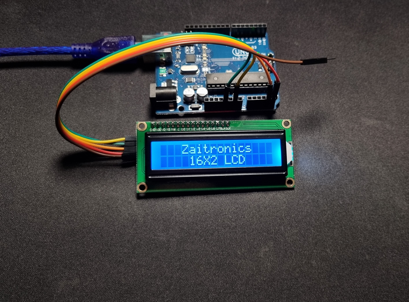
The 16X2 LCD, also commonly known as the 1602 LCD, is one of the most widely used LCD screens in electronics projects and embedded systems. It is named for its 16 columns and 2 rows, meaning it can display up to 32 characters at a time. This guide will walk you through the features, wiring, and basic programming of the 16X2 LCD.
Display
The main focus point would obviously be the display. Featuring a 16-character by 2-line configuration, the 1602 LCD provides ample space for displaying text and simple graphics. Each character is formed in a 5x8 pixel matrix, allowing for clear and legible text. Here are some key aspects of the display:
- Character Structure: Each of the 32 characters (16 per line) is composed of a 5x8 dot matrix. This structure allows for the detailed rendering of alphanumeric characters, punctuation, and even custom icons.
- Backlight: Most 1602 LCDs come with an LED backlight, which significantly improves visibility in low-light conditions. The backlight can usually be controlled via software or by adjusting the current-limiting resistor.
- Contrast: The contrast of the display can be adjusted using the VO pin, which is typically connected to a potentiometer. This allows for fine-tuning of the display's readability based on ambient lighting conditions.
- Viewing Angle: The LCD is designed to offer a wide viewing angle, ensuring that the display is readable from various positions. This is particularly useful in embedded applications where the display's orientation might not always be directly in front of the user.
- Response Time: The response time of the 1602 LCD is fast enough for most text display applications, making it suitable for real-time data display such as clocks, counters, and status messages.
Custom Characters
One of the standout features of the 1602 LCD is its ability to display custom characters. This is particularly useful for creating special symbols or icons that are not part of the standard ASCII character set. Here’s how you can create and display custom characters:
- Define Custom Characters: Custom characters are defined using a byte array, where each byte represents a row of the 5x8 pixel matrix.
- Upload to CGRAM: The custom characters are uploaded to the LCD’s Character Generator RAM (CGRAM). The HD44780 controller allows for up to 8 custom characters to be stored in CGRAM.
- Display Custom Characters: Once defined and uploaded, custom characters can be displayed using their corresponding ASCII codes.
Pinout Diagram
A standard 16x2 character LCD has 16 pins. Here’s a brief overview of each pin:

| Pin No. | Name | Description |
| 1 | GND (Ground) | Connect to ground (0V). |
| 2 | VCC (Power Supply) | Connect to the LCD’s power supply (usually 5 volts). |
| 3 | Vo (LCD Contrast) | Adjust the contrast using a potentiometer. |
| 4 | RS (Register Select) | Separates commands (e.g., setting the cursor, clearing the screen) from data. Set to LOW for commands and HIGH for data. |
| 5 | R/W (Read/Write) | Determines whether data is read from or written to the LCD. Typically held LOW for write operations. |
| 6 | E (Enable) | Enables the display. Set to LOW to ignore activity on other lines; set to HIGH to process incoming data. |
| 7-14 | D0-D7 (Data Bus) | These pins carry the 8-bit data sent to the display. For example, to display an uppercase ‘A’, set these pins to 0100 0001 (according to the ASCII table). |
| 15 | A (5V) | LED Backlight VCC |
| 16 | K (Ground) | LED Backlight Ground |
Serial Interface (I2C) for Simplified Connection
The standard 16x2 character LCDs use 7 digital pins for communication. However, you can simplify the connection by using an I2C (serial) interface. The I2C interface makes the connection cleaner and more efficient, especially when working with limited pins or multiple devices.
An I2C serial LCD reduces the required pins to just 2:
- SDA (Serial Data): Connects to the Arduino’s data line.
- SCL (Serial Clock): Connects to the Arduino’s clock line.
- GND (Ground): Connects to the Arduino’s ground pin.
- VCC (5V): Connects to the Arduino’s 5V.
- VCC to 5V
- GND to GND
- SDA to A4
- SCL to A5
Conclusion
The 1602 LCD is an essential component for displaying text and basic graphics in many electronic projects. Its ease of use, coupled with features like custom characters and adjustable contrast, makes it a versatile and powerful display solution. Whether you're building a simple project or a complex embedded system, understanding how to leverage the capabilities of the 1602 LCD will greatly enhance your ability to create informative and user-friendly interfaces.