
L298N Dual H Bridge Motor Driver
L298N Dual H Bridge Motor Driver has a 5-10 day lead time before dispatch. Order will only be sent once all items are available for delivery.
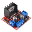
L298N Dual H Bridge Motor Driver
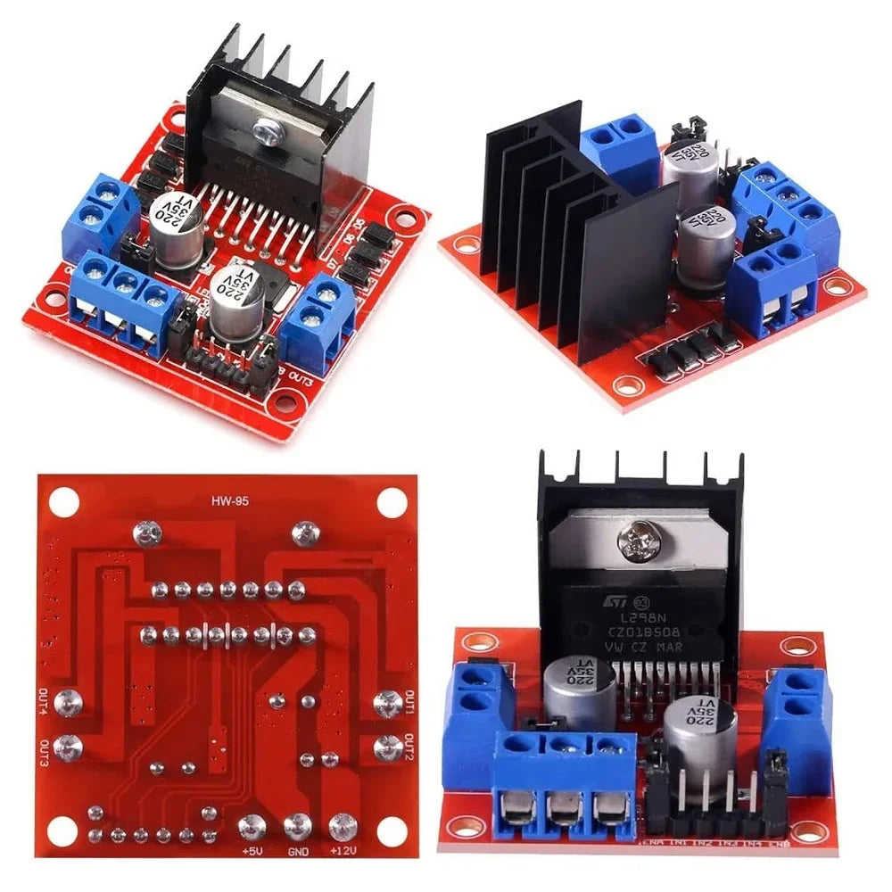
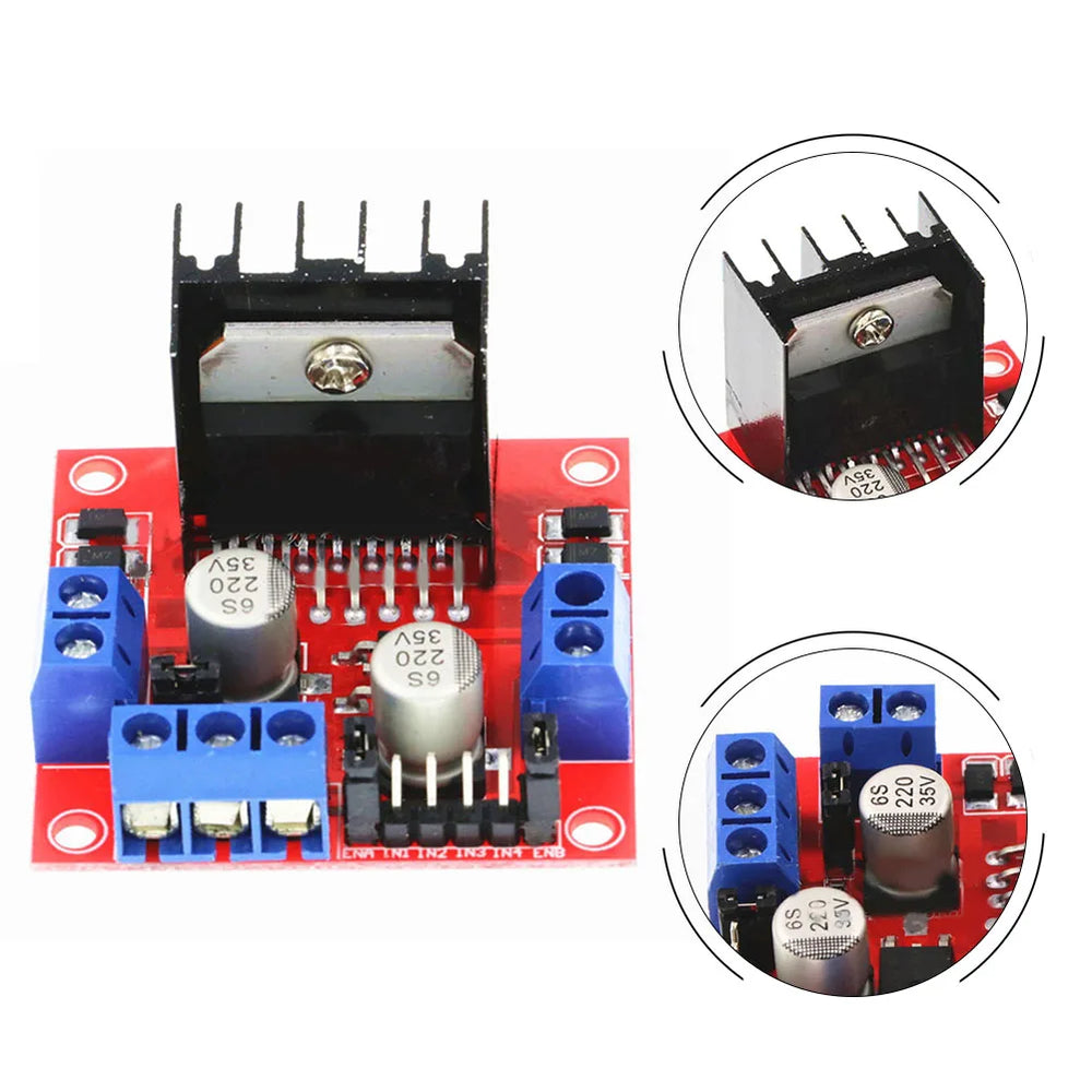
Control the speed and direction of DC and stepper motors with this L298N Dual H-Bridge Motor Driver Module. Based on the popular L298N Motor Driver IC, this module can independently drive two DC motors or a single bipolar stepper motor, making it ideal for Arduino robots, RC vehicles, automation projects, CNC machines, and DIY electronics. Compatible with Arduino, ESP32, Raspberry Pi, STM32 and other microcontrollers, the module provides simple bidirectional motor control using standard digital I/O pins.
The onboard 78M05 voltage regulator allows the module to power your microcontroller when operating from a 7V to 12V motor supply, while large filter capacitors and built-in protection diodes improve reliability during operation. Screw terminals make wiring quick and secure, making the L298N one of the most popular motor driver modules for beginners and experienced makers alike.
Features
- Dual H-Bridge motor driver for controlling two DC motors or one bipolar stepper motor
- Based on the popular L298N Dual H-Bridge Motor Driver IC
- Motor supply voltage from 5V to 35V DC
- Up to 2A output current per motor channel
- Independent speed and direction control for each motor
- PWM speed control using ENA and ENB pins
- Built-in 5V regulator for powering logic circuits (7V to 12V input)
- Screw terminals for secure wiring
- Large heatsink for improved heat dissipation
- Compatible with Arduino, ESP32, Raspberry Pi and other microcontrollers
How the L298N Dual H-Bridge Works
The L298N contains two independent H-Bridge circuits, allowing it to control two DC motors simultaneously or one bipolar stepper motor. Each H-Bridge reverses the polarity supplied to the motor, enabling forward and reverse rotation. Motor speed is controlled using Pulse Width Modulation (PWM) on the ENA and ENB enable pins, while the IN1 to IN4 control pins determine the direction of rotation.
Because the L298N uses bipolar transistor technology, there is typically a voltage drop of around 2V across each H-Bridge. For example, a 12V motor may require approximately 14V at the motor supply input to achieve its full rated voltage.
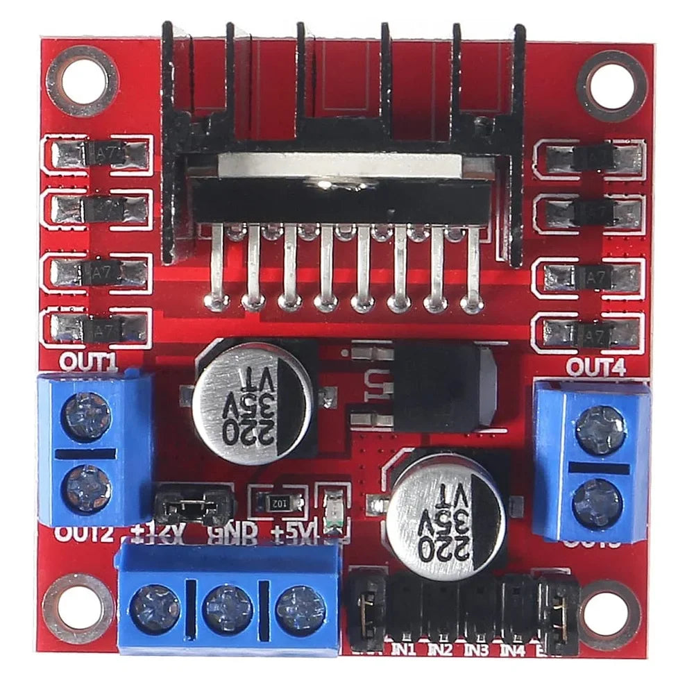
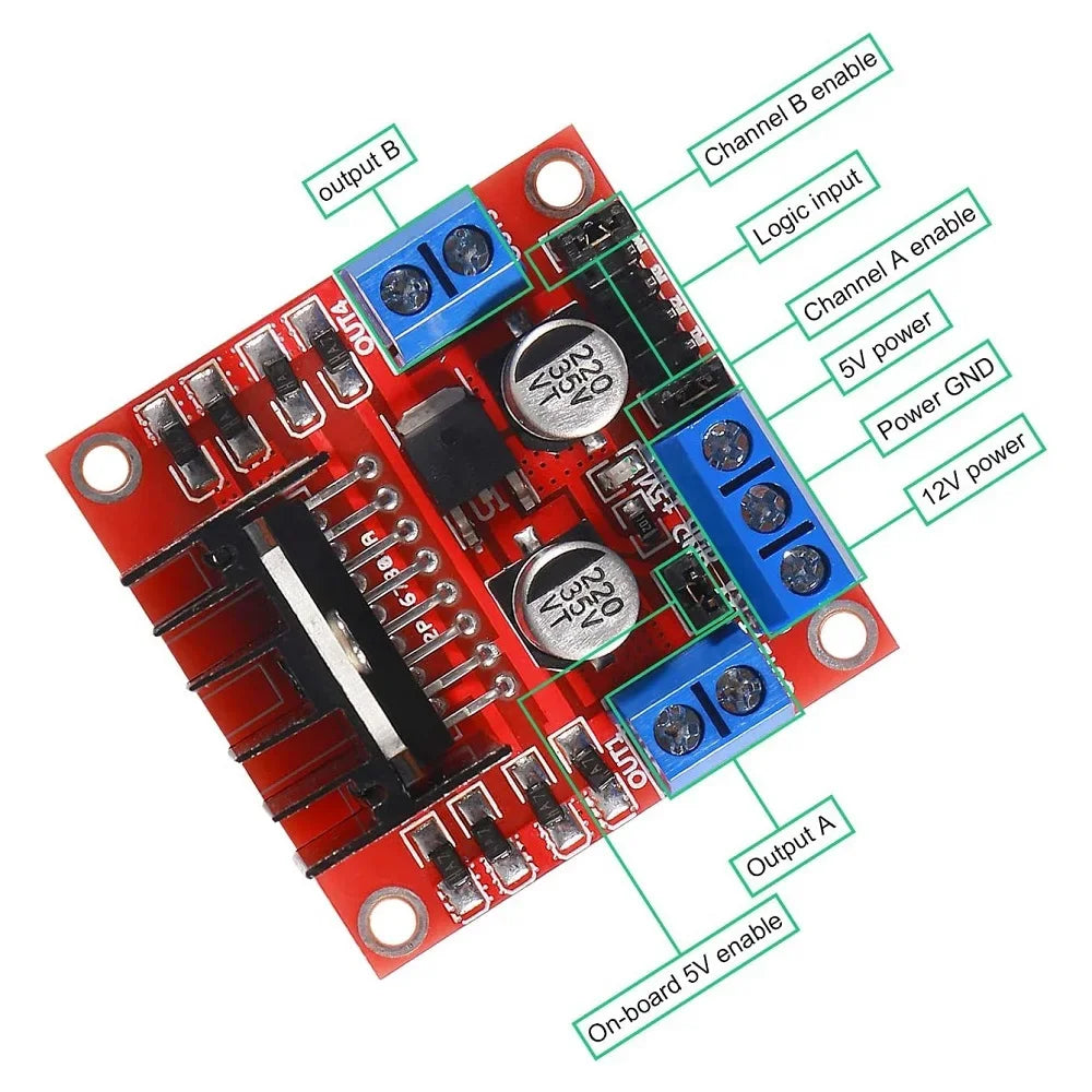
Pinout & Connections
| Pin | Function | Description |
|---|---|---|
| VS | Motor Power | 5V to 35V motor supply input |
| GND | Ground | Common ground for motor and logic power |
| 5V | Logic Power | 5V logic supply or regulated 5V output (jumper dependent) |
| ENA | Enable A | PWM speed control for Motor A |
| IN1 | Direction A | Motor A direction input |
| IN2 | Direction A | Motor A direction input |
| IN3 | Direction B | Motor B direction input |
| IN4 | Direction B | Motor B direction input |
| ENB | Enable B | PWM speed control for Motor B |
| OUT1 / OUT2 | Motor A | Output terminals for Motor A |
| OUT3 / OUT4 | Motor B | Output terminals for Motor B |
Motor Direction Truth Table
| IN1 | IN2 | Motor A |
|---|---|---|
| LOW | LOW | Stopped |
| HIGH | LOW | Forward |
| LOW | HIGH | Reverse |
| HIGH | HIGH | Stopped |
Motor B operates identically using the IN3 and IN4 inputs.
Specifications
- Motor Driver IC: L298N
- Driver Type: Dual H-Bridge
- Motor Supply Voltage: 5V to 35V DC
- Logic Voltage: 5V
- Maximum Output Current: 2A per channel
- Maximum Output Power: 25W
- Motor Channels: 2 DC motors or 1 bipolar stepper motor
- Control Inputs: ENA, IN1, IN2, IN3, IN4, ENB
- Onboard Voltage Regulator: 78M05
- Operating Temperature: -20°C to +135°C
- Dimensions: 69 × 56 × 36mm
- Weight: Approximately 30g
Applications
- Arduino robot cars
- Line following robots
- Obstacle avoidance robots
- RC vehicles
- Stepper motor control
- Conveyor and automation systems
- DIY CNC machines
- Motorised projects and prototypes
- Educational electronics projects
Important Notes
- The onboard 5V regulator can be used only when the motor supply is between 7V and 12V.
- For motor supply voltages above 12V, remove the 5V regulator jumper and supply an external regulated 5V logic source.
- The L298N has an inherent voltage drop of approximately 2V due to the H-Bridge transistors.
- Although rated for up to 2A per channel, additional cooling may be required during continuous high-current operation.
Documentation
This product can be found here:
