
1
of
5
Loading...
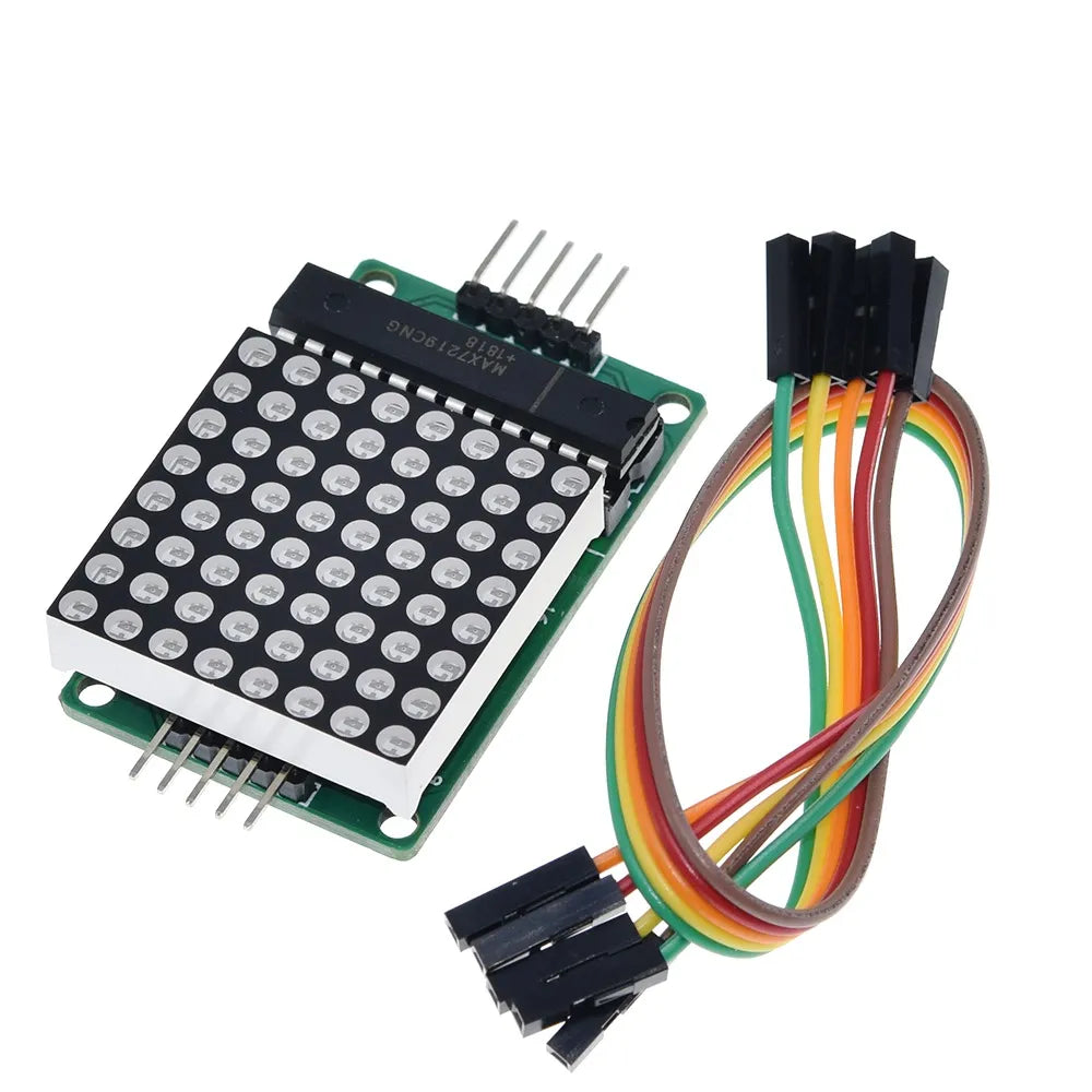
Red LED Matrix MAX7219
Zaitronics | SKU:
Z0104
$6.50 AUD
Unit price
/
Unavailable
$5.91 exc GST
Red LED Matrix MAX7219 has a 5-10 day lead time before dispatch. Order will only be sent once all items are available for delivery.
★
★
★
★
★
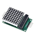
Red LED Matrix MAX7219
$6.50 AUD
Unit price
/
Unavailable
The MAX7219 simplifies driving LED displays, making it ideal for applications such as scoreboards, clocks, and scrolling text displays. Its compact design and ease of use make it a favourite among hobbyists and electronics enthusiasts.
Features:
- Integrated Serial Input/Output Common-Cathode Display Driver:
- The MAX7219 is designed to interface microprocessors (μPs) with 7-segment numeric LED displays, bar-graph displays, or individual LEDs.
- BCD Code-B Decoder:
- On-chip BCD code-B decoder for efficient data handling.
- Multiplex Scan Circuitry:
- Enables multi-channel scanning and word drive.
- 8x8 Static RAM:
- Stores data for each digit.
- Segment Current Control:
- Only one external register needed to set the segment current for all LEDs.
- Serial Interface:
- Convenient four-wire serial interface compatible with most general-purpose microprocessors.
- Coding Options:
- Allows the user to select coding or non-coding for each data.
- Low-Power Shutdown Mode:
- Contains a 150μA low-power shutdown mode.
- Brightness Control:
- Analog and digital brightness control.
- Scan-Limit Register:
- Allows displaying from 1 to 8 digits.
- LED Light Detection Mode:
- Provides an option to light up all LEDs.
Module Parameters:
- Common Cathode Lattice:
- A single module can drive an 8x8 common cathode lattice.
- Operating Voltage:
- Module operates at 5V.
- Module Size:
- Dimensions: 5cm (length) x 3.2cm (width) x 1.5cm (height).
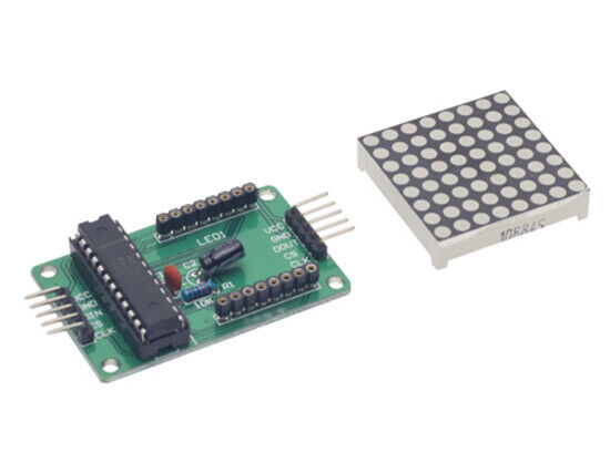
- Mounting Holes:
- Four screw holes with a 3mm aperture for secure installation.
- Cascading Support:
- Input and output interfaces allow multiple modules to be cascaded.
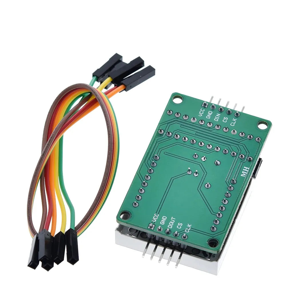
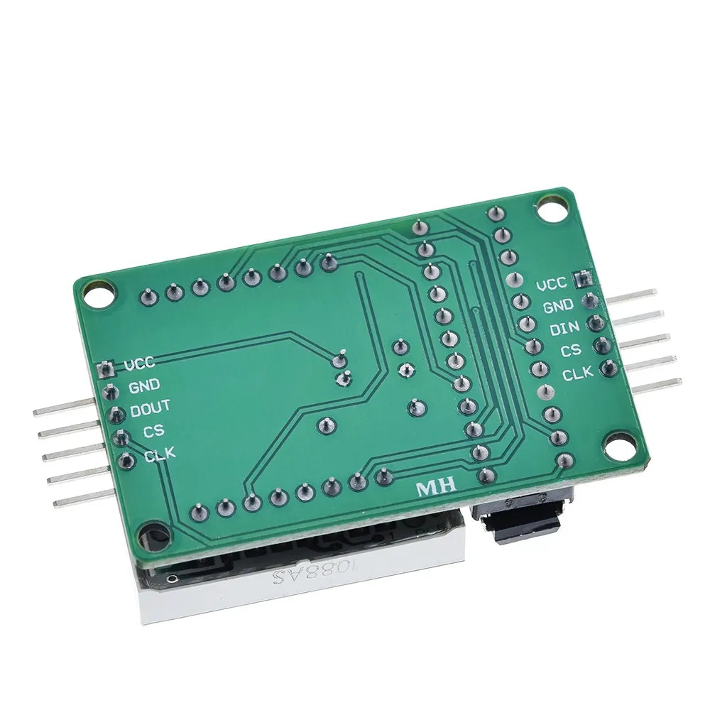
Wiring Instructions:
- Connect the module’s input port (left side) and output port (right side).
- For controlling a single module:
- Connect the input port directly to the CPU.
- For cascading multiple modules:
- Input termination module connects to the CPU.
- Output termination module connects to the input of the next module.
- Repeat this pattern for additional modules.
Example for an MCU (e.g., Arduino UNO):
- VCC: Connect to 5V
- GND: Connect to GND
- DIN: Connect to P22
- CS: Connect to P21
- CLK: Connect to P20
This product can be found here:
