
Digispark ATtiny85 USB Development Board
Digispark ATtiny85 USB Development Board has a 5-10 day lead time before dispatch. Order will only be sent once all items are available for delivery.
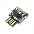
Digispark ATtiny85 USB Development Board
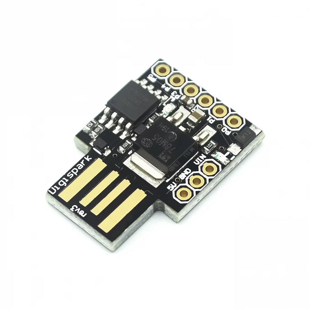
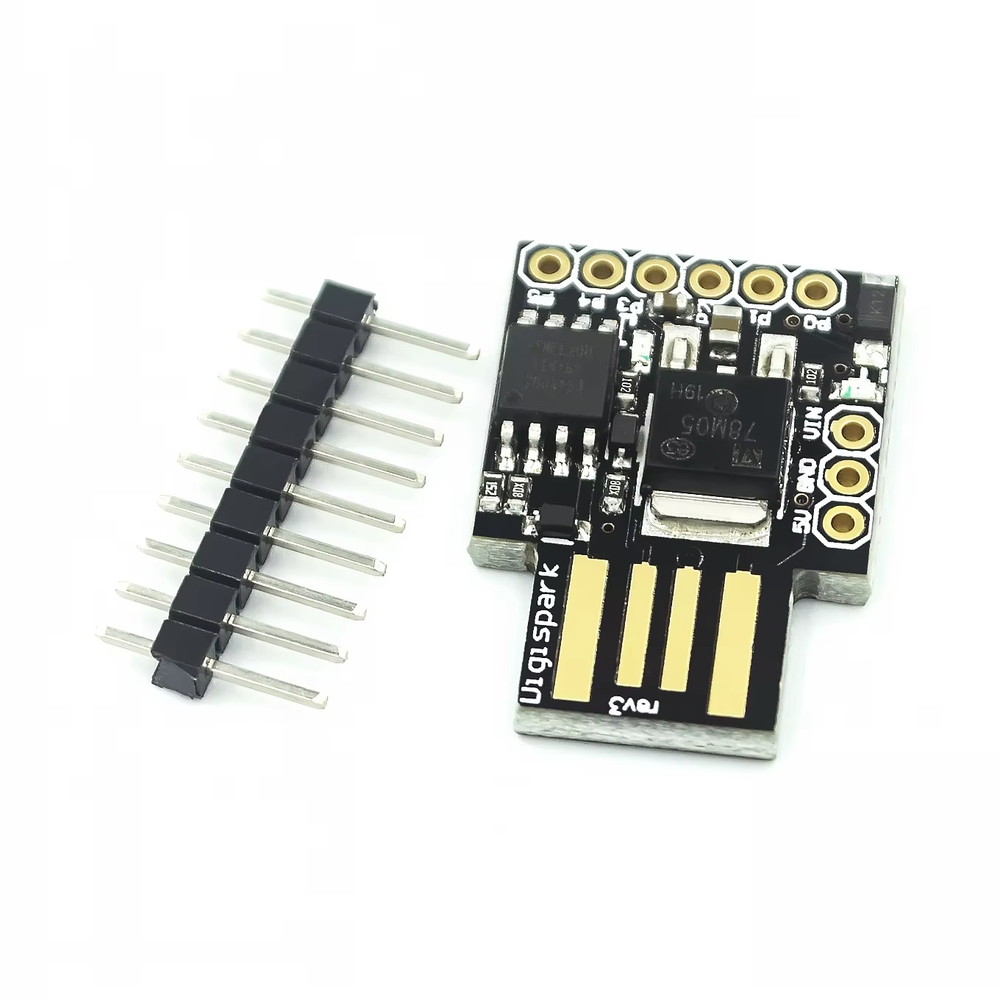
The Digispark ATtiny85 USB Development Board is a tiny, low-cost microcontroller board that plugs straight into a USB port and programs from the Arduino IDE. Built around the ATtiny85, it's ideal for small projects where a full Arduino is overkill, such as USB keyboard and HID devices, LED controllers, simple sensors, and compact embedded builds.
The board has a Micro USB connector for programming and power, an onboard 5V regulator for external supplies, and 6 I/O pins with PWM, ADC, I2C and SPI support. It comes preloaded with the Micronucleus USB bootloader, so no separate programmer is needed.
Features
- ATtiny85 8-bit AVR microcontroller
- Programs directly over Micro USB with the Arduino IDE
- Powered by USB, 5V, or an external 6V to 16V supply via VIN
- Onboard 5V regulator
- 6 I/O pins (2 shared with USB)
- PWM on 3 pins, ADC on 4 pins
- I2C and SPI via the USI peripheral
- Power LED and onboard status LED
- USB protection diodes
Specifications
- Microcontroller: ATtiny85
- Flash memory: 8KB (about 6KB available after bootloader)
- SRAM: 512 bytes
- EEPROM: 512 bytes
- Clock speed: 16.5MHz
- Operating voltage: 5V
- USB power: 5V via Micro USB
- External power (VIN): 6V to 16V
- I/O pins: 6
- PWM pins: 3
- ADC: 10-bit, 4 channels
- Interfaces: I2C, SPI (via USI)
Pinout

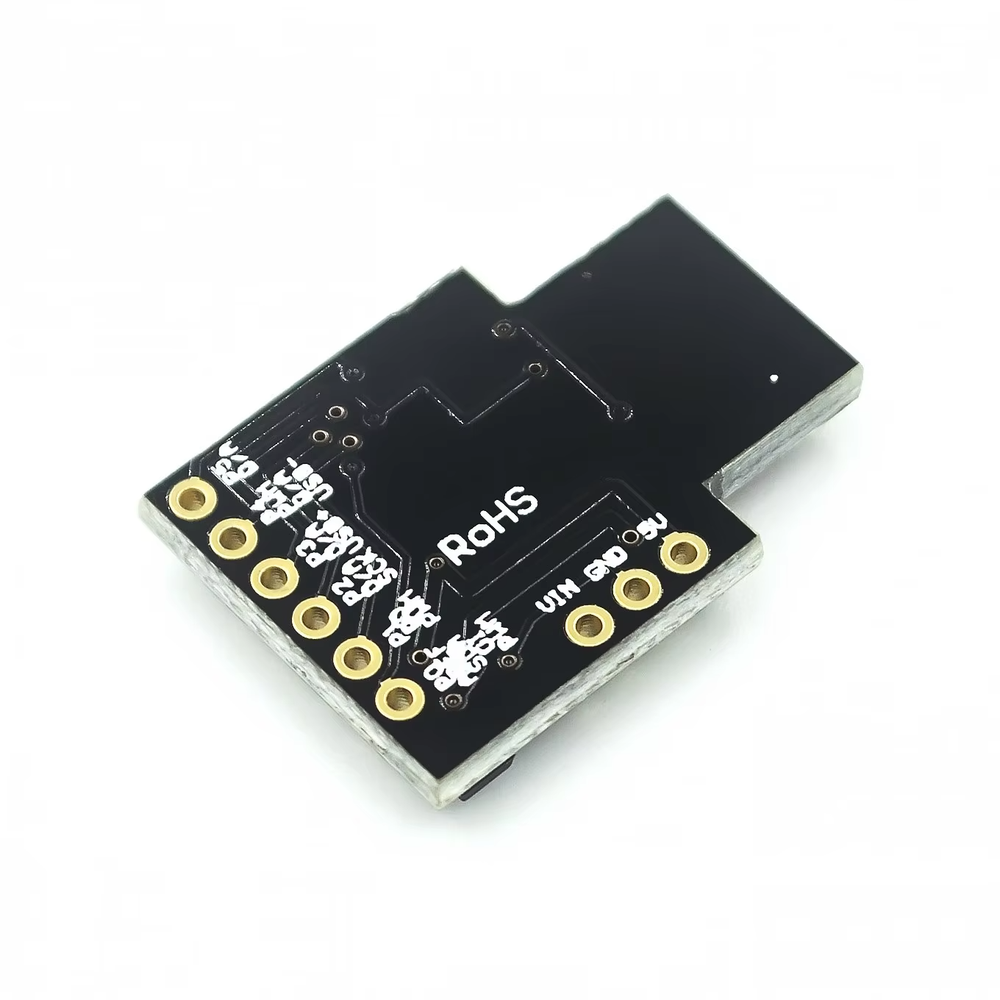
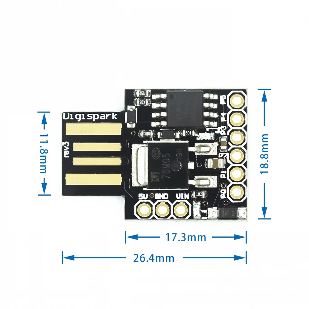
- P0: PWM, I2C SDA, SPI MOSI
- P1: PWM, SPI MISO
- P2: ADC1, I2C SCL, SPI SCK
- P3: ADC3, USB D+ (has a 1.5k pull-up resistor)
- P4: PWM, ADC2, USB D-
- P5: ADC0, Reset (limited use as I/O)
- 5V: 5V output from the regulator, or 5V input
- GND: Ground
- VIN: External power input, 6V to 16V
The onboard status LED is connected to P1 on most boards, or P0 on some revisions.
Getting Started
- Install the Digistump AVR board package in the Arduino IDE using the Boards Manager.
- Windows users will need to install the Digistump drivers for the board to be recognised.
- Click Upload first, then plug the board in when prompted. The bootloader only accepts uploads for a few seconds after connection.
Usage Notes
- The board waits about 5 seconds on power-up for the bootloader before running your sketch.
- P3 and P4 are used for USB communication. They can be used as normal I/O, but external circuits on these pins can stop the board from uploading.
- P5 is the reset pin and is best used as an analog input only.
- With only 512 bytes of SRAM, large libraries and serial-heavy sketches may not fit. For bigger projects, consider an Arduino Nano or ESP32.
Documentation
This product can be found here:
