
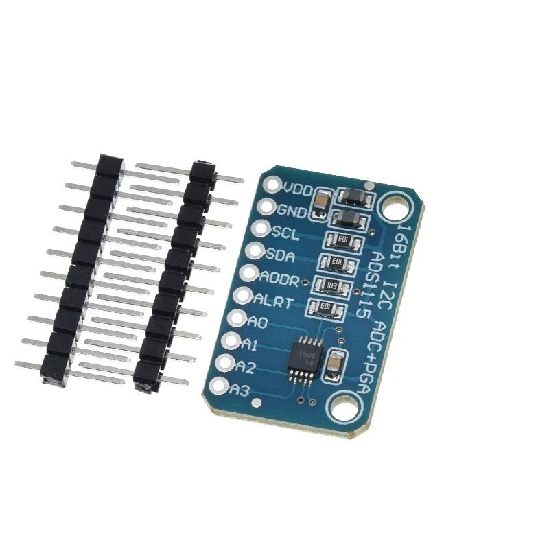


ADS1115 ADC 4 Channel Pro Gain Amplifier
ADS1115 ADC 4 Channel Pro Gain Amplifier has a 5-10 day lead time before dispatch. Order will only be sent once all items are available for delivery.
ADS1115 ADC 4 Channel Pro Gain Amplifier
The ADS1115 is a 16-bit analog-to-digital converter module with a programmable gain amplifier (PGA), built around the Texas Instruments ADS1115 IC. It reads analog signals over I2C at up to 860 samples per second, which makes it a good upgrade for boards with a limited or noisy built-in ADC, or none at all. Use it as 4 single-ended inputs or 2 differential inputs, and boost small signals with gains of up to x16. It works with Arduino, ESP32, ESP8266, Raspberry Pi and any other 2V to 5.5V I2C microcontroller.
Key Features
- 16-bit resolution
- 4 single-ended or 2 differential input channels
- Programmable gain amplifier with 6 input ranges, up to x16 gain
- Programmable data rate from 8 to 860 samples per second
- Internal low-drift voltage reference and oscillator
- Programmable comparator with ALERT/RDY output pin
- Pin-selectable I2C address, so up to 4 modules can share one bus (16 single-ended inputs)
- Low power: 150µA in continuous mode, with automatic shutdown in single-shot mode
- Wide supply range of 2.0V to 5.5V, so it works with both 3.3V and 5V logic
Specifications
- ADC: Texas Instruments ADS1115, 16-bit
- Supply voltage: 2.0V to 5.5V
- Channels: 4 single-ended (A0 to A3) or 2 differential
- Data rate: 8 to 860 SPS
- Interface: I2C
- I2C addresses: 0x48 to 0x4B (set with the ADDR pin)
Input Ranges
The PGA sets the full-scale input range. Smaller ranges give finer resolution for small signals.
- ±6.144V
- ±4.096V
- ±2.048V (default)
- ±1.024V
- ±0.512V
- ±0.256V
Important: the voltage on any input pin must stay between GND and VDD (plus 0.3V). The ±6.144V and ±4.096V ranges are scaling options only, so with a 5V supply you can measure up to about 5V, and with a 3.3V supply up to about 3.3V. Single-ended readings only use the positive half of the range, so their effective resolution is 15 bits. Differential readings use the full 16 bits.
Pinout

- VDD: 2.0V to 5.5V supply, use your logic voltage
- GND: Ground
- SCL: I2C clock
- SDA: I2C data
- ADDR: I2C address select
- ALRT: Comparator alert / conversion ready output
- A0 to A3: Analog inputs
Changing the I2C Address
The address is set by where the ADDR pin is connected. Using several modules on one bus gives you up to 16 single-ended inputs.
- ADDR to GND: 0x48 (default)
- ADDR to VDD: 0x49
- ADDR to SDA: 0x4A
- ADDR to SCL: 0x4B
Getting Started
Connect GND to ground, VDD to your logic supply and SCL/SDA to your microcontroller's I2C pins. On an Arduino Uno or Nano, SDA goes to A4 and SCL to A5. Install the Adafruit ADS1X15 library for Arduino, or the Adafruit CircuitPython ADS1x15 library for Raspberry Pi, and run the included examples.
Applications
- Sensor interfacing for temperature, pressure, light and similar analog sensors
- Industrial automation and process monitoring
- Data acquisition and scientific measurement
- IoT projects that need accurate analog readings
- Adding precision analog inputs to boards like the Raspberry Pi, which has none
Package Includes
- 1 x ADS1115 16-bit 4-channel ADC module with programmable gain amplifier
- 1 x 10-pin male header
Documentation
This product can be found here:
